H4.X Module
For Modular Open Systems Approach (MOSA) flight and mission computing applications
At a glance
- Architecture
- Single channel
- Mass
- 200 g
- Power
- 8 W maximum
- Isolation
- Non-isolated
- RTOS
- ARINC 653 Part 1
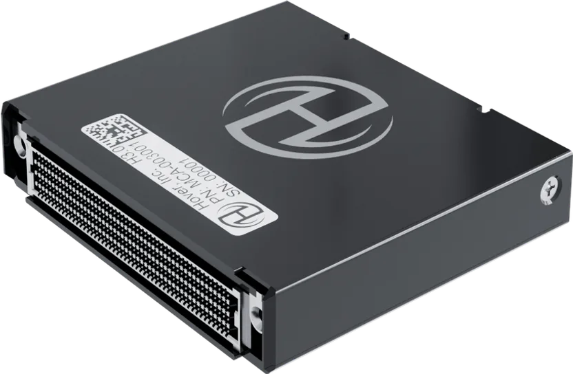
Drag to rotate, scroll to zoom
The H4.X Module plugs into a VNX+ (VITA 90) chassis for flight and mission computing in a Modular Open Systems Approach (MOSA) architecture. US law (10 U.S.C. § 4401) states that major defense acquisition programs “shall be designed and developed, to the maximum extent practicable, with a modular open system approach to enable incremental development and enhance competition, innovation, and interoperability.”
Key capabilities
- Backward and forward compatibility: VNX+ (VITA 90) standardizes electrical and mechanical interfaces; therefore, the H4.X is compatible with every VNX+ chassis.
- Designed for certification: the hardware and software are designed to Development Assurance Level (DAL) A, with environmental qualification to RTCA DO-160G at chassis level.
- Future-proof upgrades: MOSA and DO-297 incremental acceptance support independent upgrades of hardware and software at the module level.
- Software portability: with the Future Airborne Capability Environment (FACE) and PYRAMID, software applications are redeployable between H-series computers, VNX+ systems, and other conformant platforms without a rewrite.
System integration
In a VNX+ system, the H4.X Module hosts flight or mission software alongside other VNX+ modules in a common chassis, sharing utility functions across the backplane.
Modular platform
The H-series computers are modular by design and share the same H-RTOS and H-SDK. The H4.X is compatible with every H-series main processing board, including the safety-critical and edge inference boards.
Specifications
Physical
5 items
| Form factor | VNX+ (VITA 90) small form factor module |
|---|---|
| Dimensions | 89 × 78 × 19 mm |
| Mass | 200 g |
| Cooling | Conduction-cooled through the VNX+ chassis |
| Mounting | Plug-in module, retained by two captive screws |
Electrical
4 items
| Input voltage | 12 V DC from the VNX+ backplane |
|---|---|
| Power consumption | 6.4 W typical, 8 W maximum |
| Galvanic isolation | Non-isolated, optimized for size, weight, and cost |
| Connectors | VNX+ (VITA 90) backplane connector |
Processing
4 items
H4.0
| Main processing board | Safety-critical |
|---|---|
| Processors | 2 × Arm Cortex-A72 @ 800 MHz |
| Memory and storage | 16 GB SDRAM and 1 GB NOR flash |
| Design assurance | DAL A |
H4.1
| Main processing board | Edge inference |
|---|---|
| Processors | 2 × Arm Cortex-A76 @ 1.8 GHz and 2 × Arm Cortex-A55 @ 1.5 GHz |
| Memory and storage | On-board eMMC |
| Design assurance | DAL C |
Specifications are typical values and subject to change. Contact us for the controlled datasheet before committing to a design.
Interfaces
Ethernet
2 × 1 GbE, IEEE 802.1 TSN
CAN FD
4
EIA-485
1, half-duplex, 50 Mbps
Analog inputs
8
General-purpose I/O
10 inputs / 10 outputs
Power
12 V input and ground from the VNX+ backplane
Interface availability and channel counts vary by configuration. Full pin-level detail is provided in the Interface Control Document.
Design assurance and qualification
- RTCA DO-160G environmental qualification at chassis level
- RTCA DO-178C Development Assurance Level A (software)
- RTCA DO-254 Development Assurance Level A (complex hardware)
- RTCA DO-297 integrated modular avionics guidance
- TSO-C153a Integrated Modular Avionics (IMA) approval
Typical applications
- MOSA flight computer
- MOSA mission computer
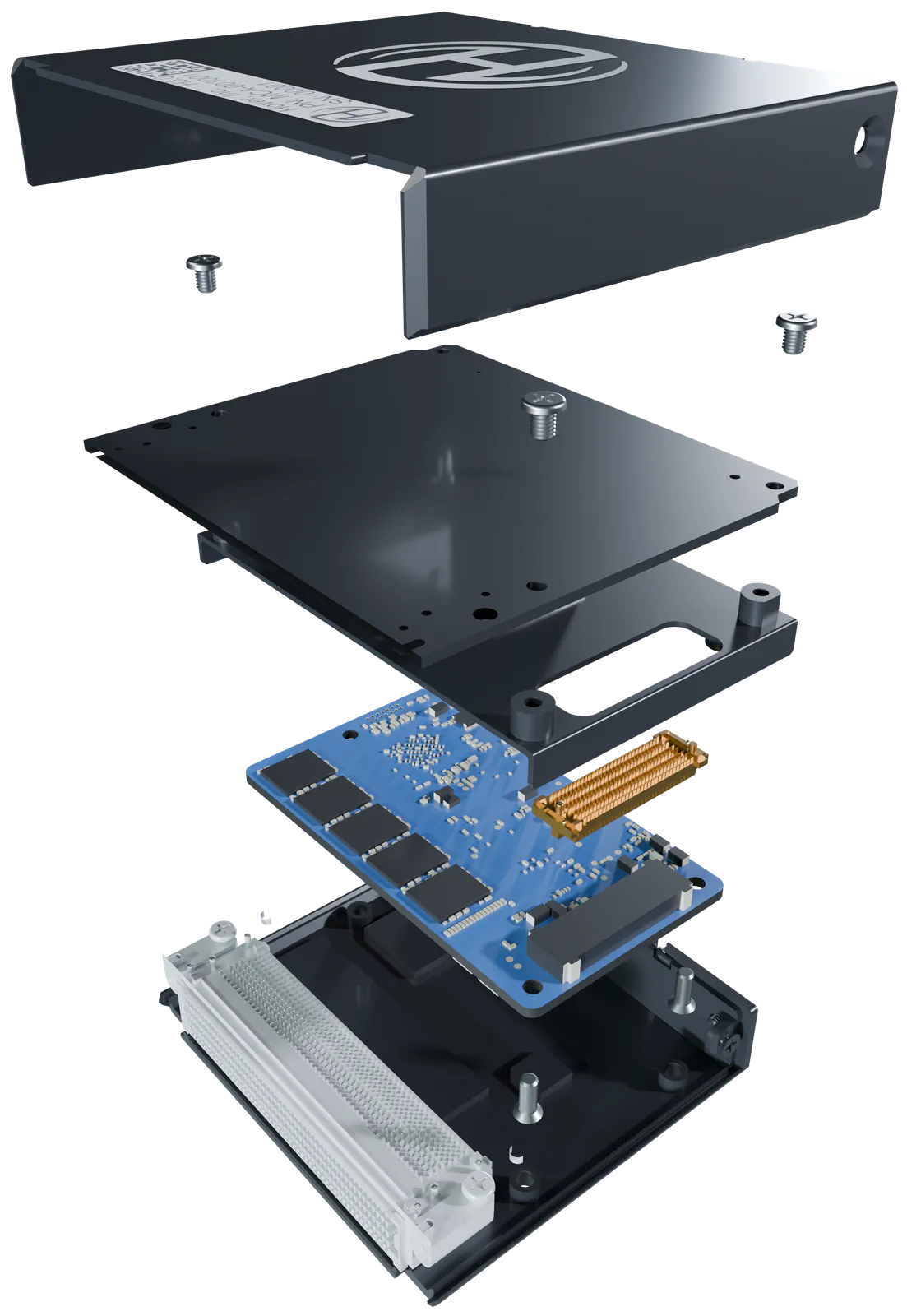
Inside the H4.X
Request the full datasheet
Our engineering team can provide the complete datasheet, 3D Computer-Aided Design (CAD) STEP models, and the electrical and mechanical Interface Control Document (ICD) under a Non-Disclosure Agreement (NDA).